Share This


Test Blog
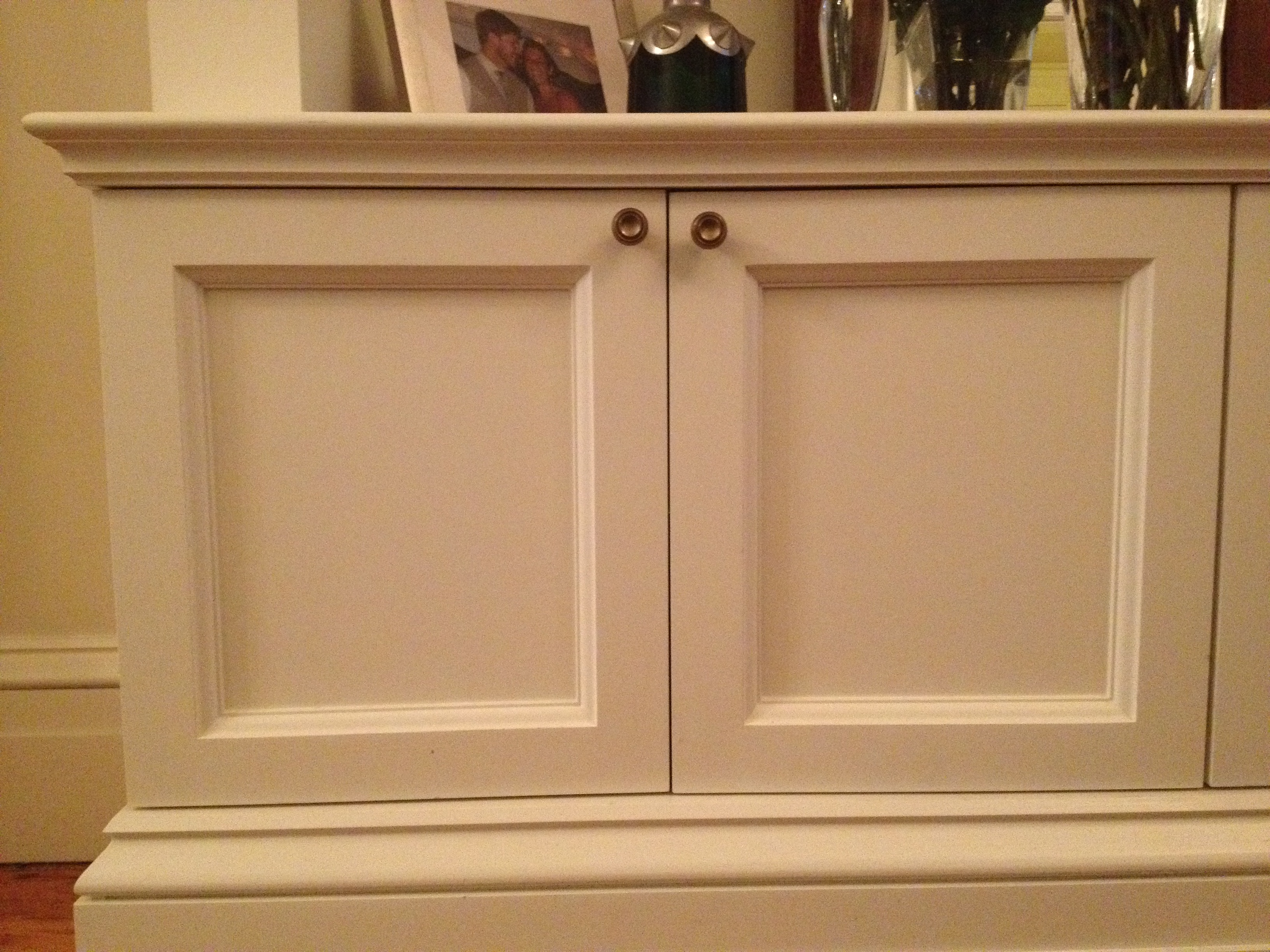
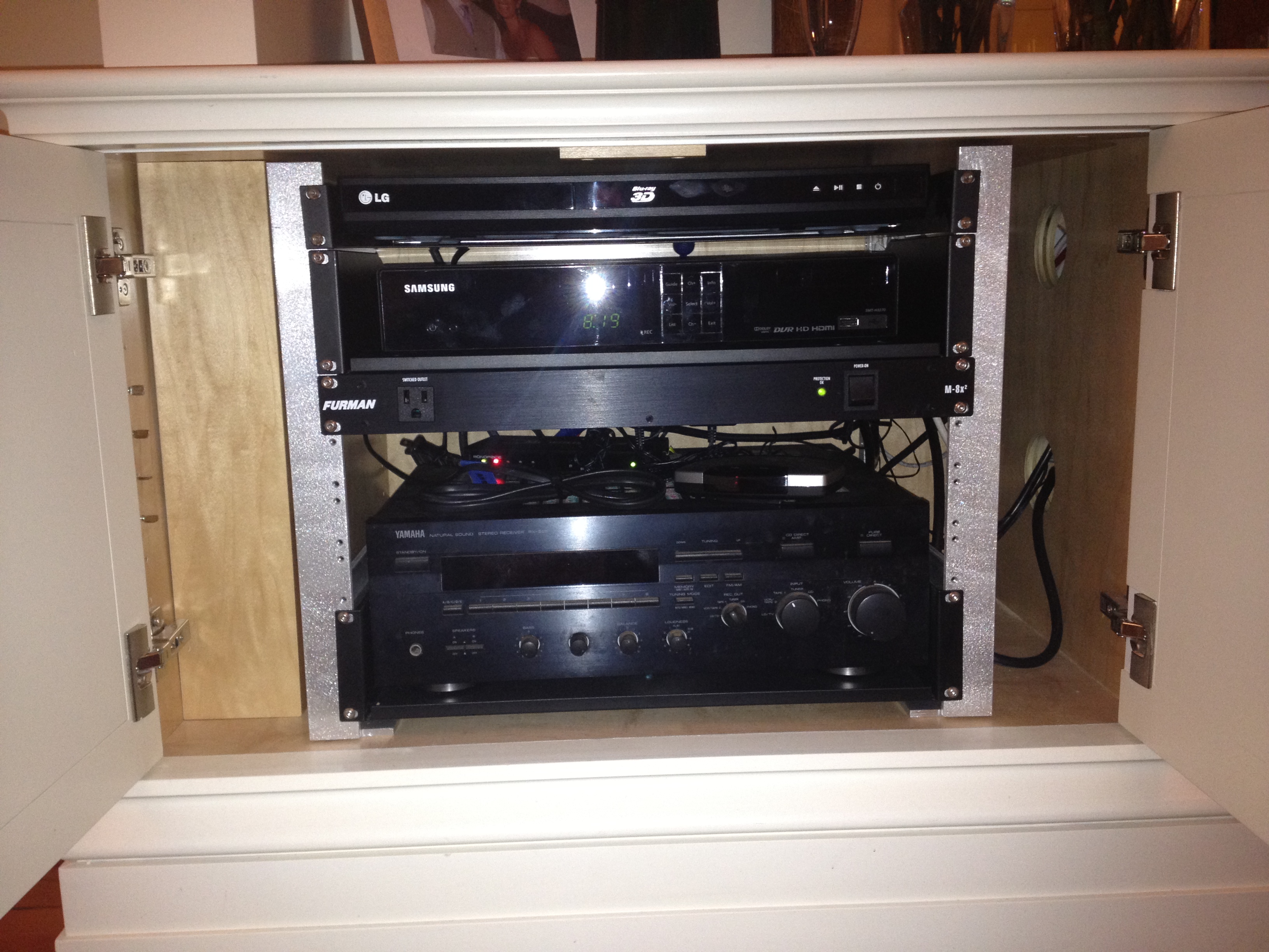
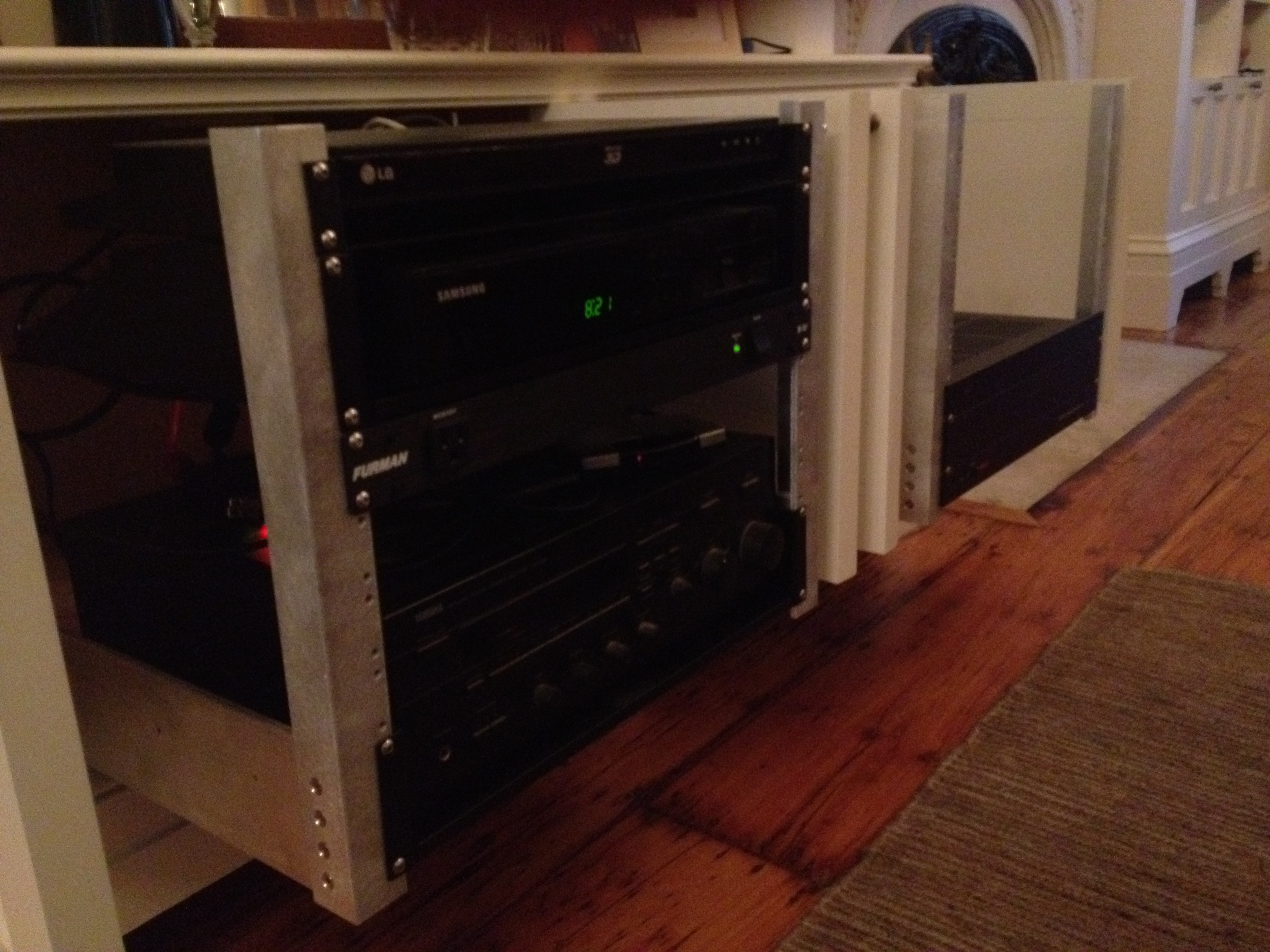
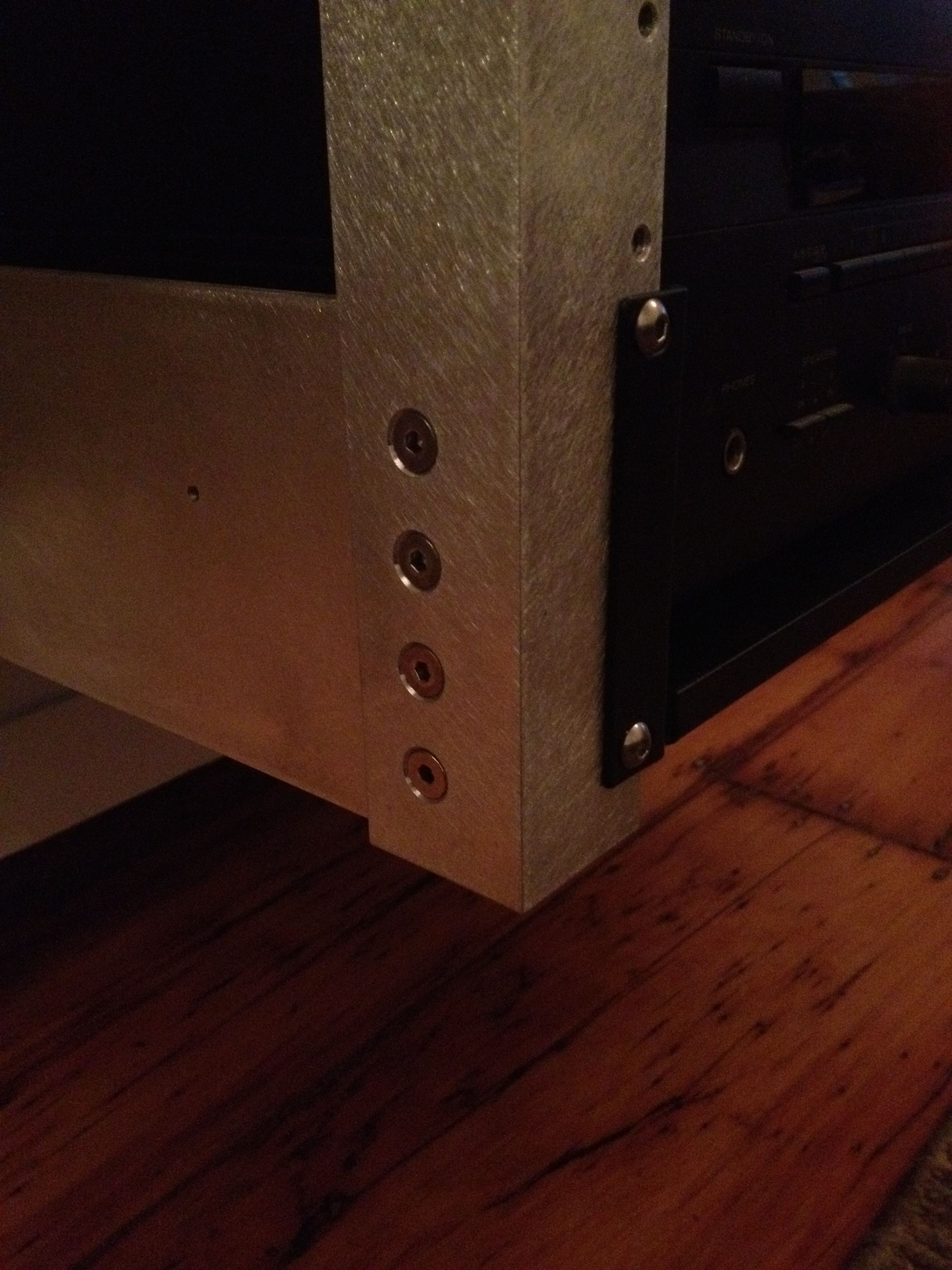
19″ A/V Rack
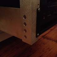
Pull out A/V rack that allows access to rear of components for easy wiring and configuration. Standard 19″ rack width accommodates items with rack ears as well as readily available shelves.
6061 aluminum, ball bearing sliders, and stainless steel fasteners.
Bedside Tables
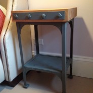
Bedside tables. Butcher block top with square nut fastened side plates and steel base.
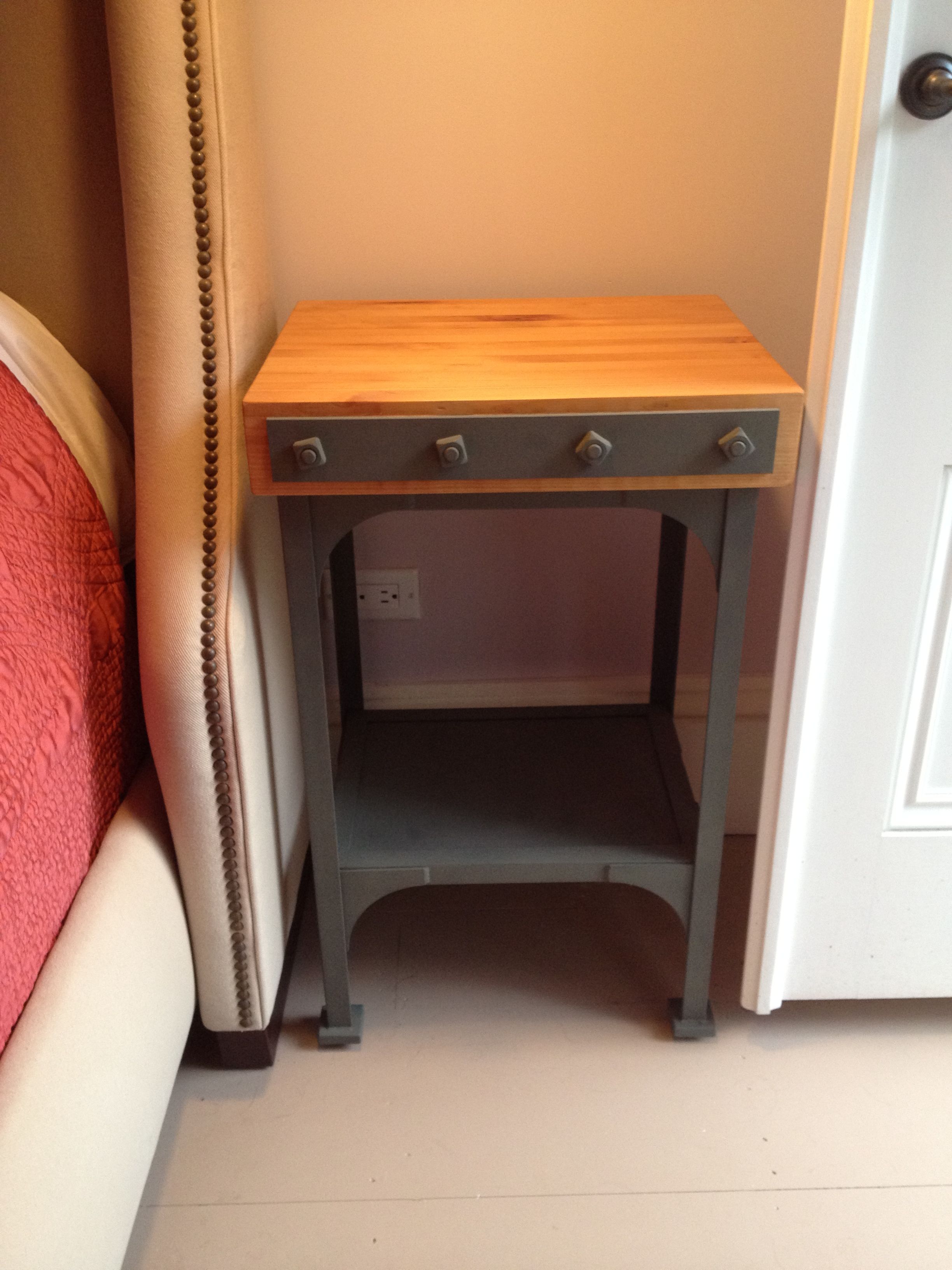
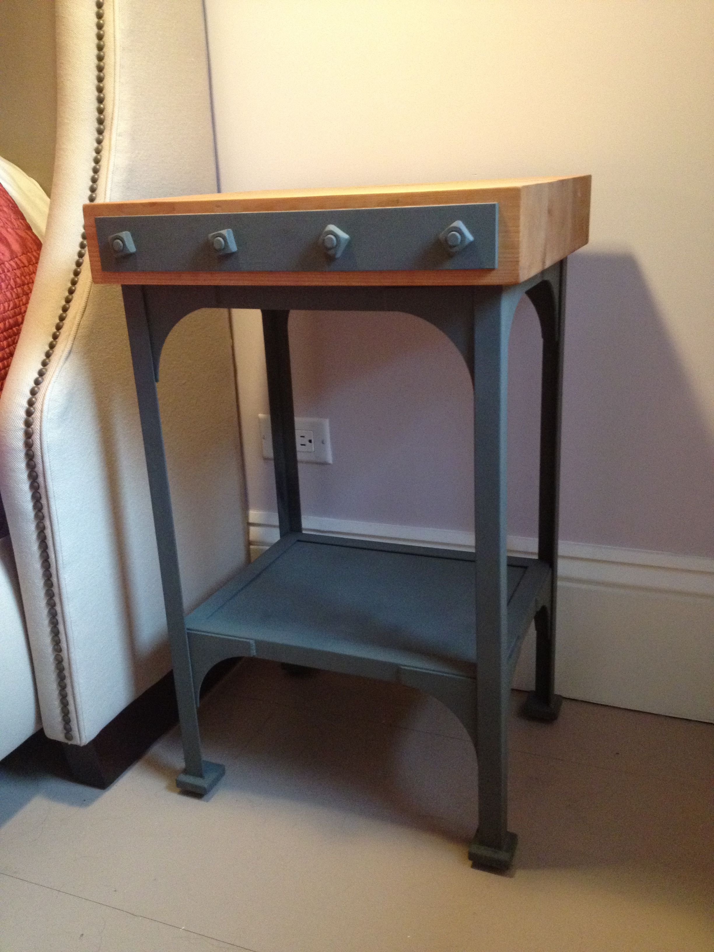
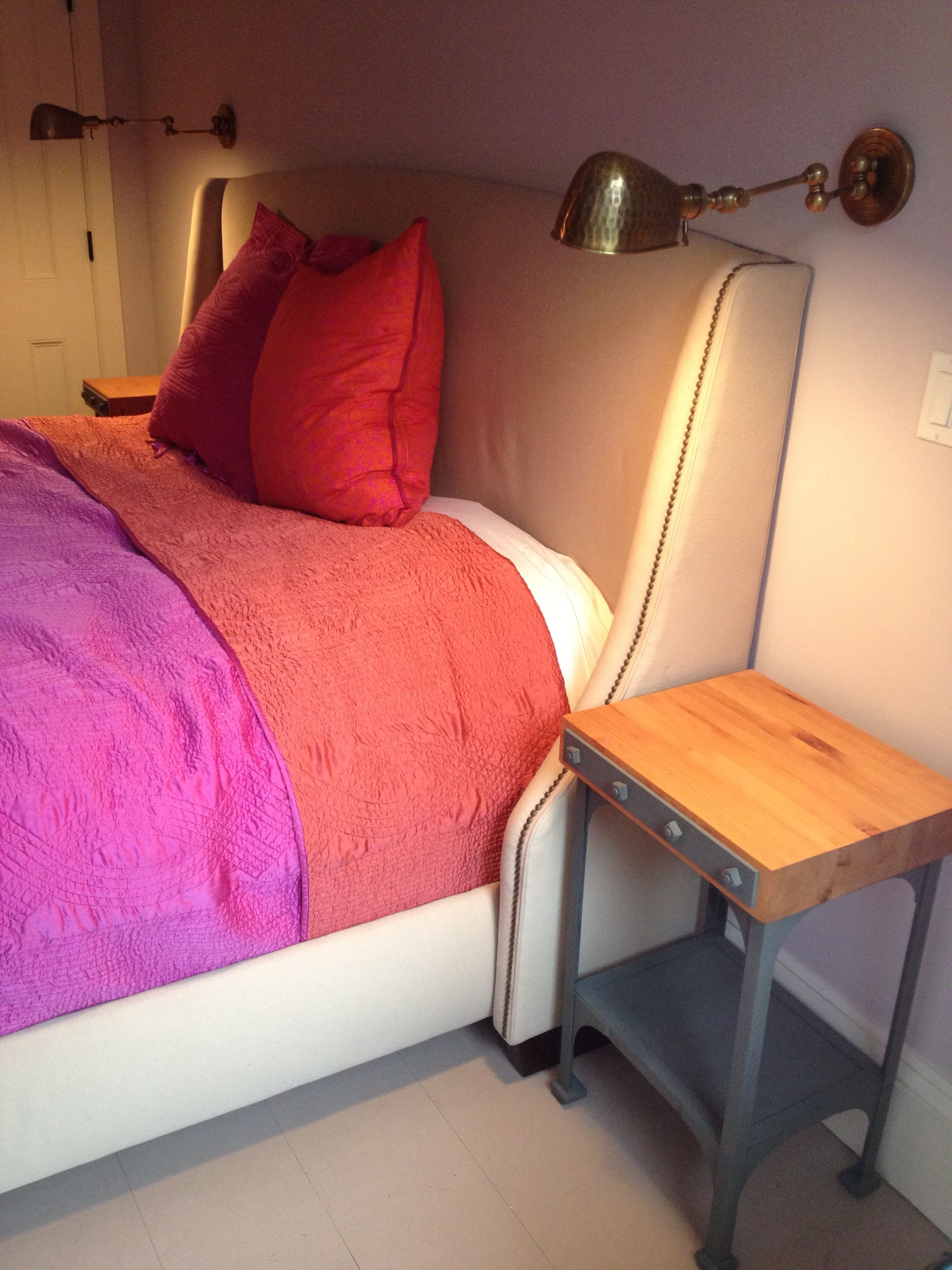
Steel and reclaimed wood.
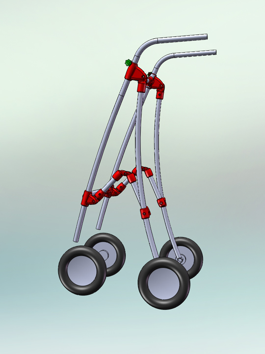
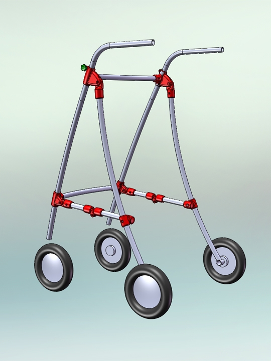
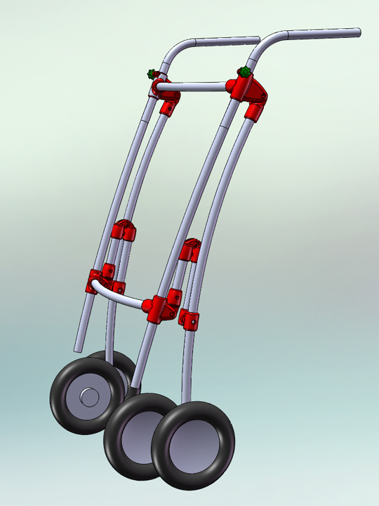
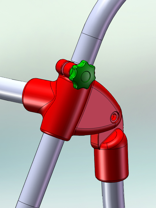
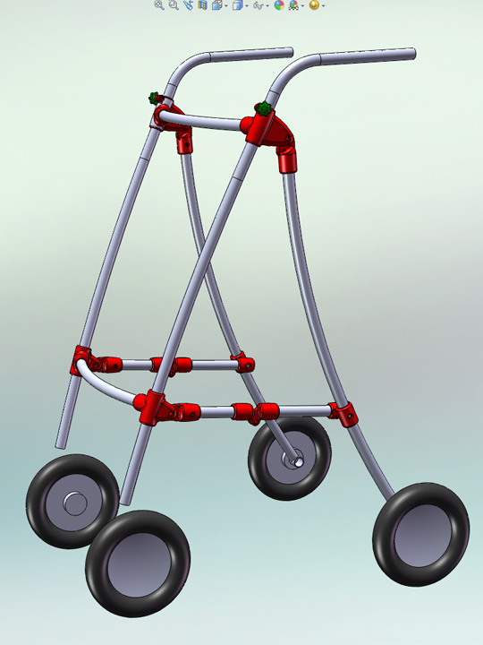
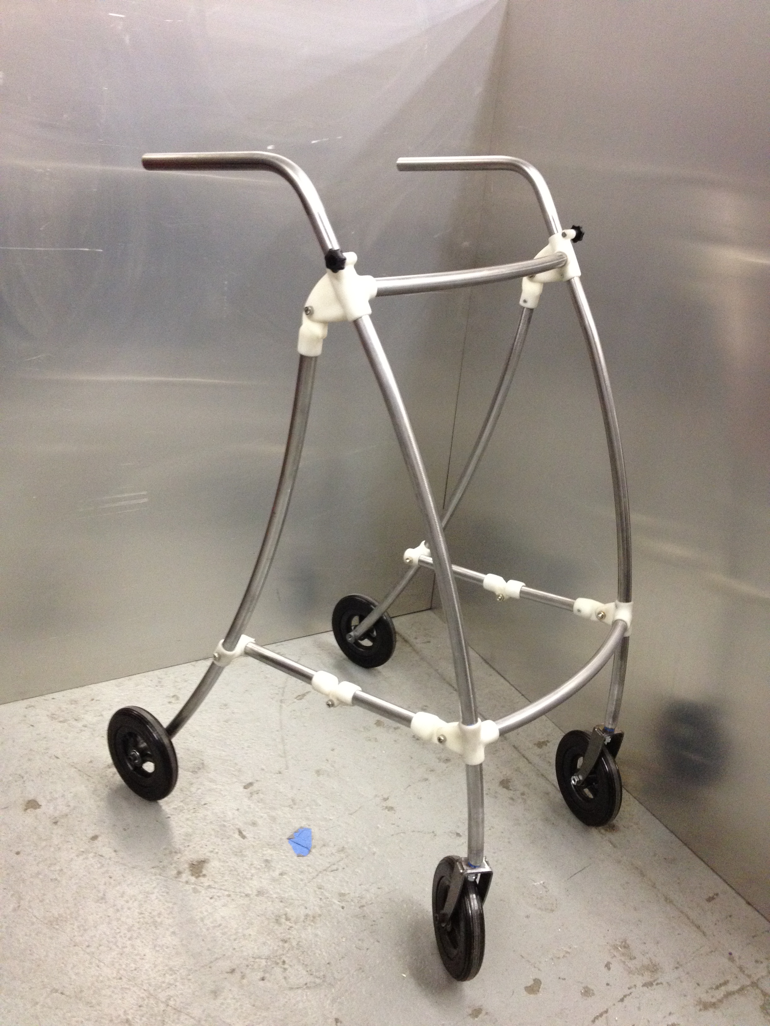
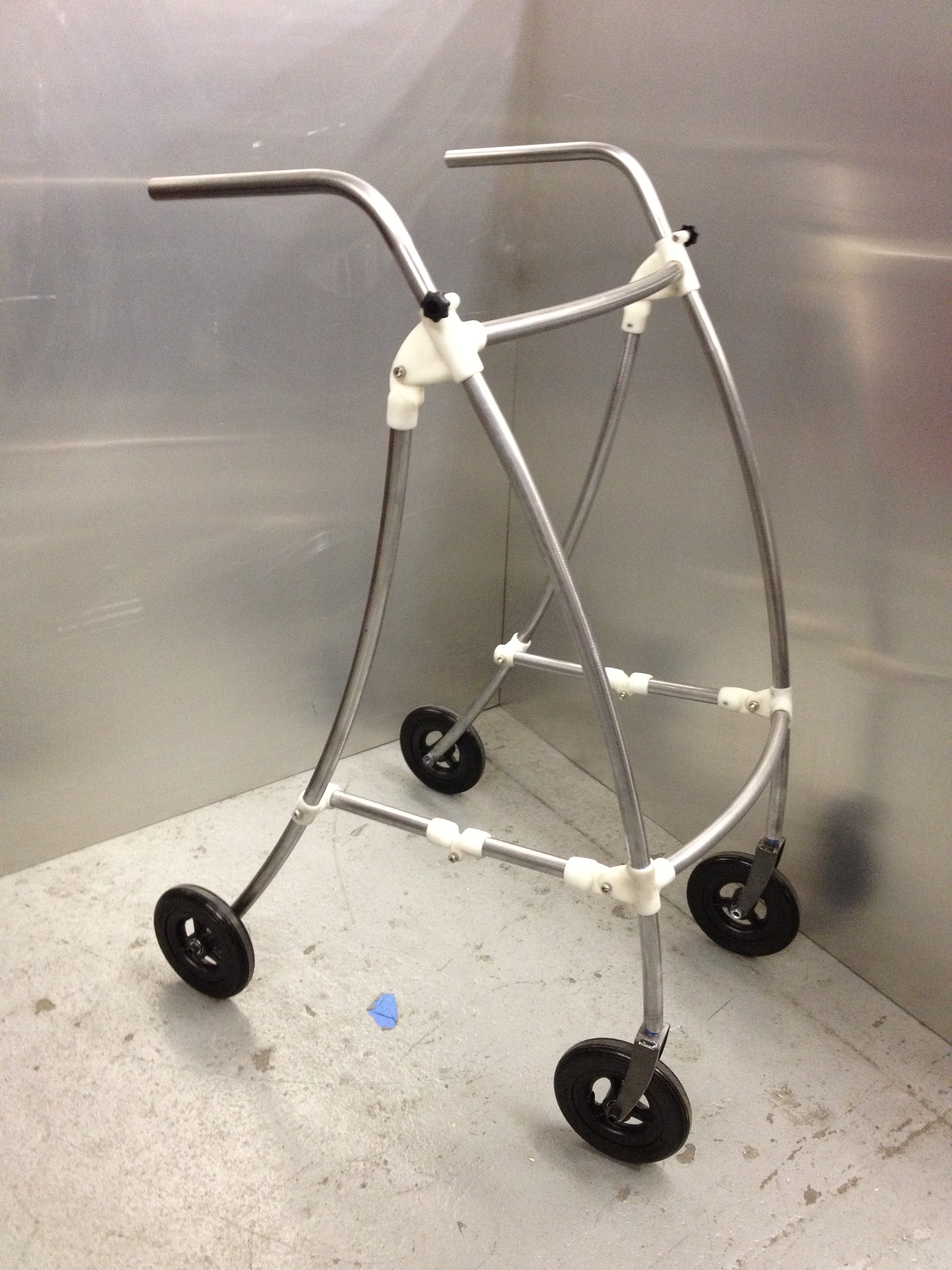
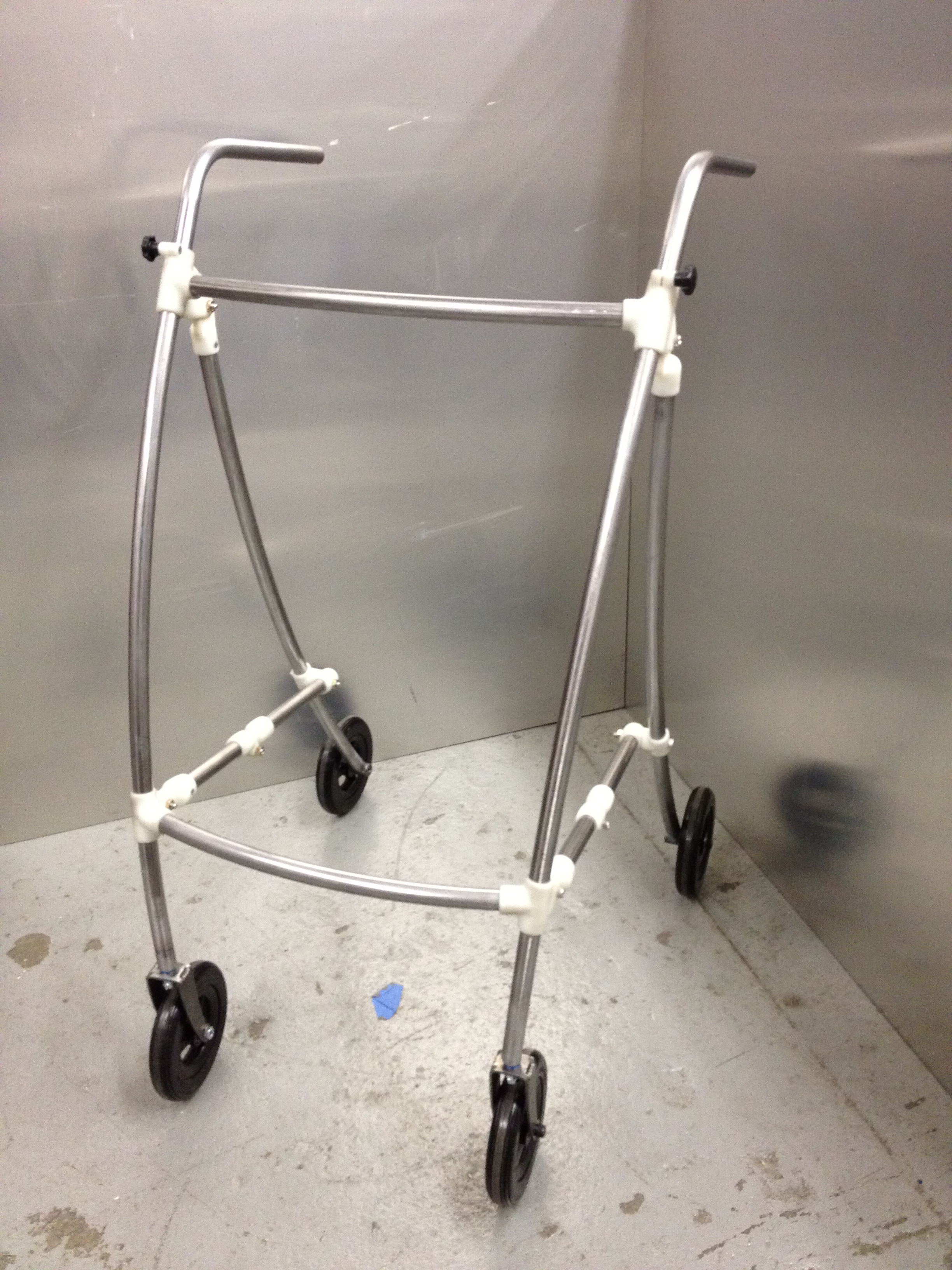
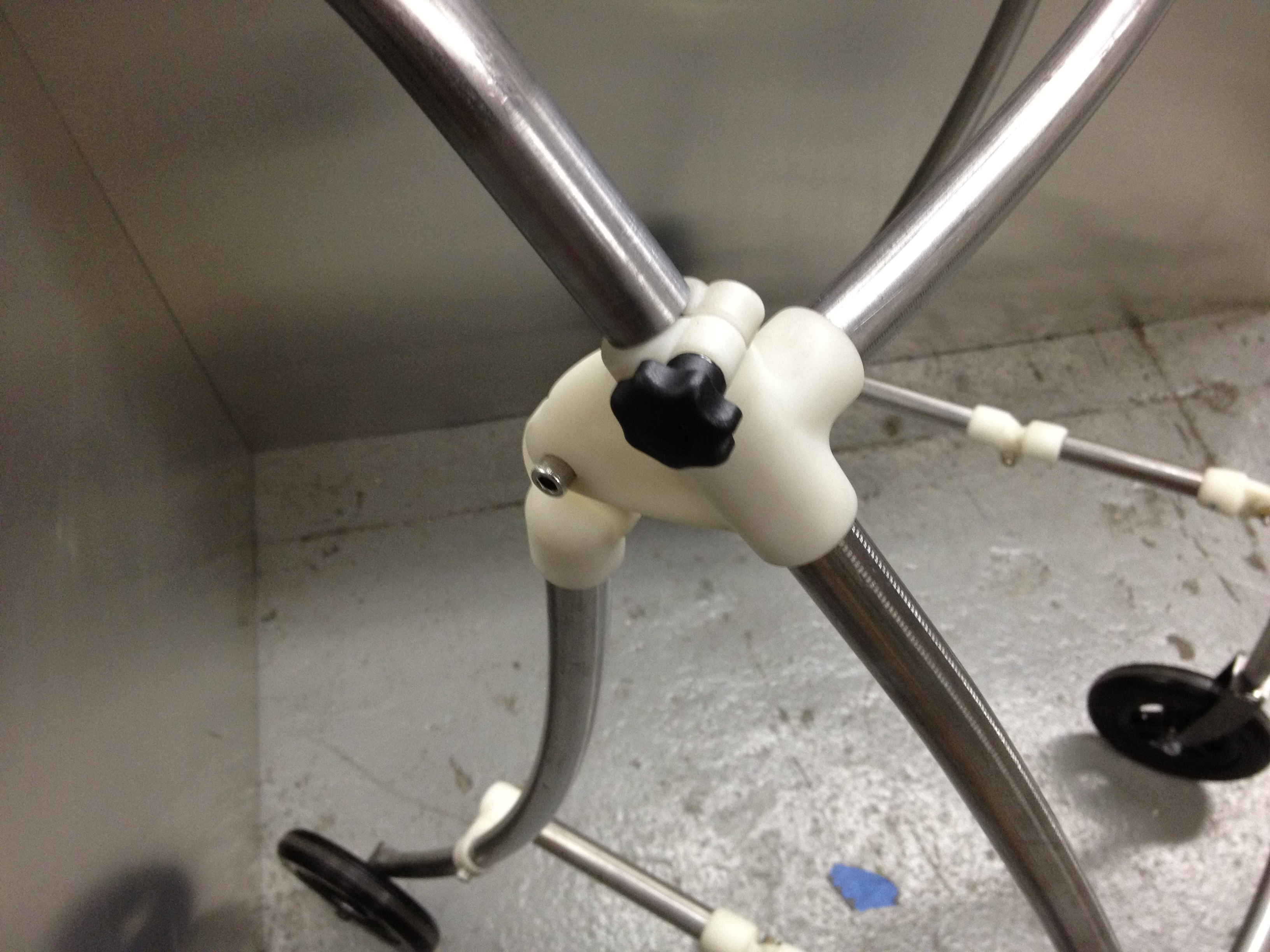
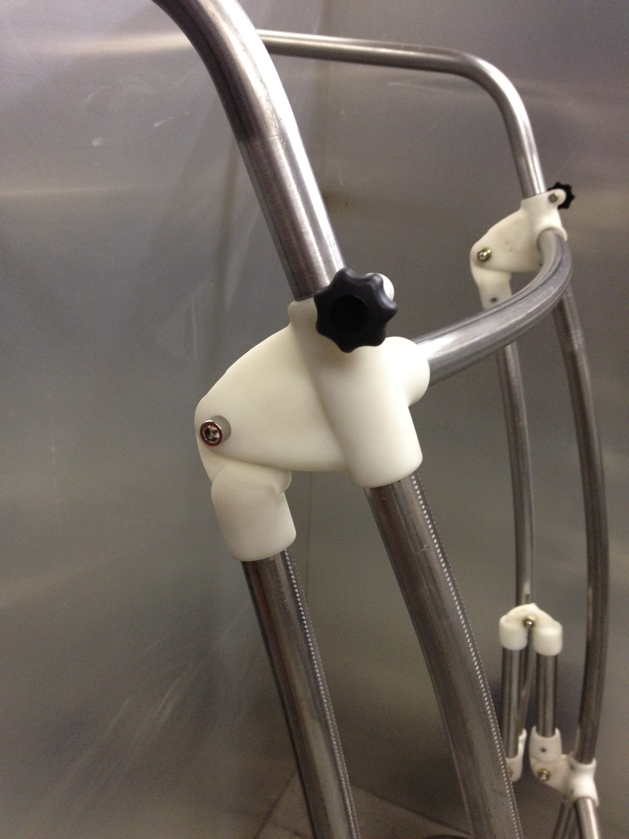
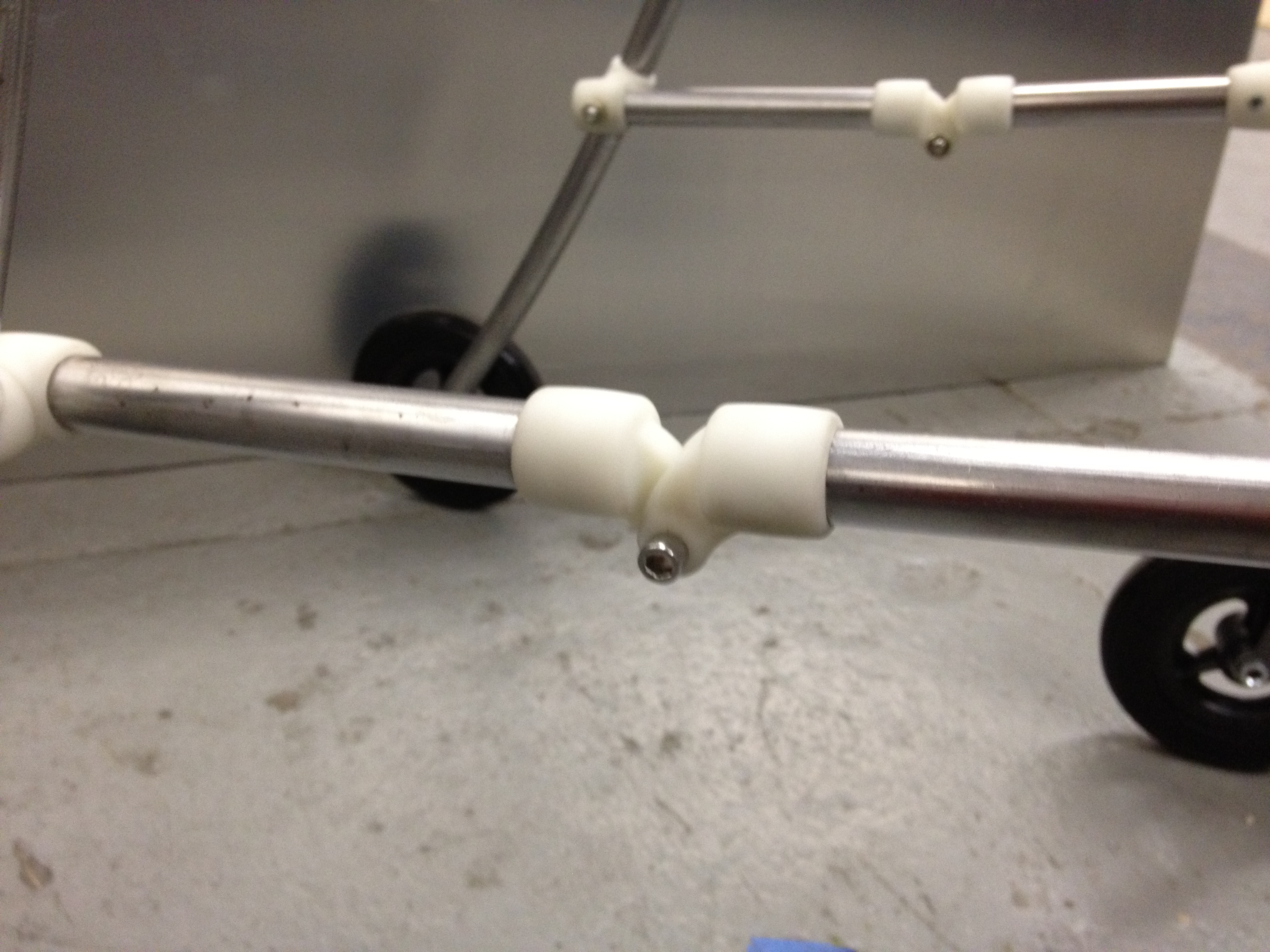
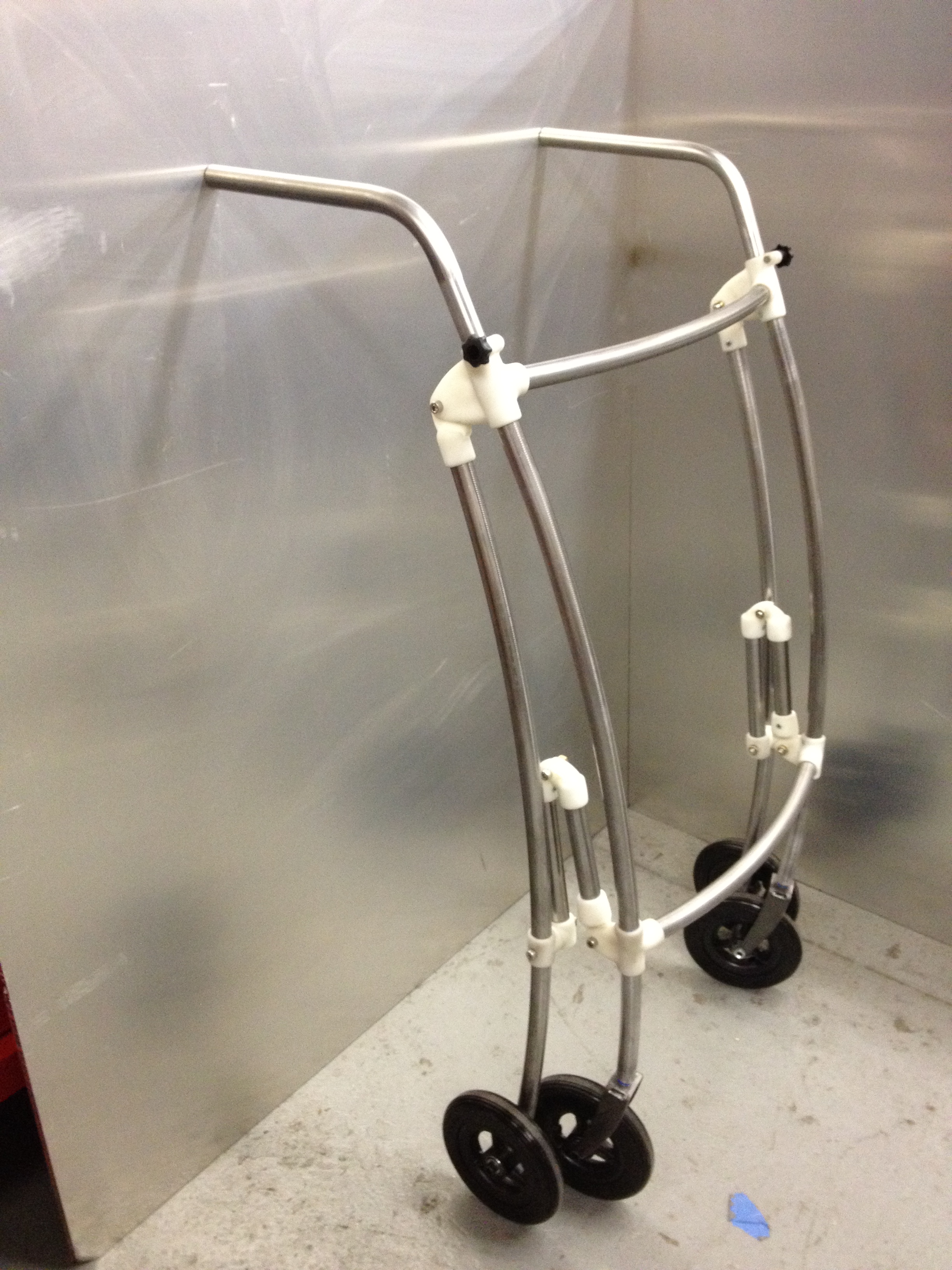
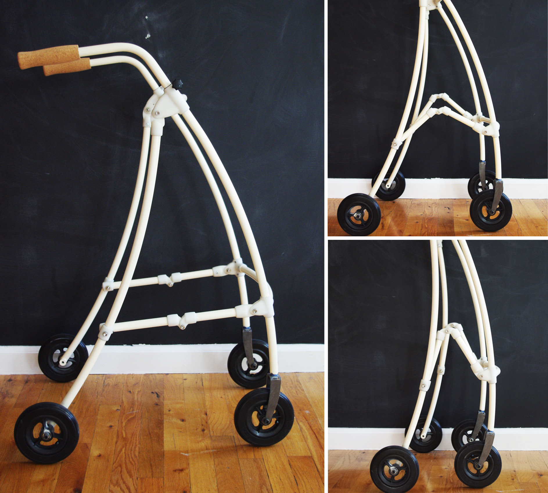
Carla’s Walker
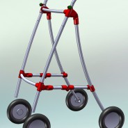
We designed and prototyped the plastic hinges and bent the tubes for this folding shopping cart / walker.
Steel and SLS Plastic.
Tennis Ball Cannon
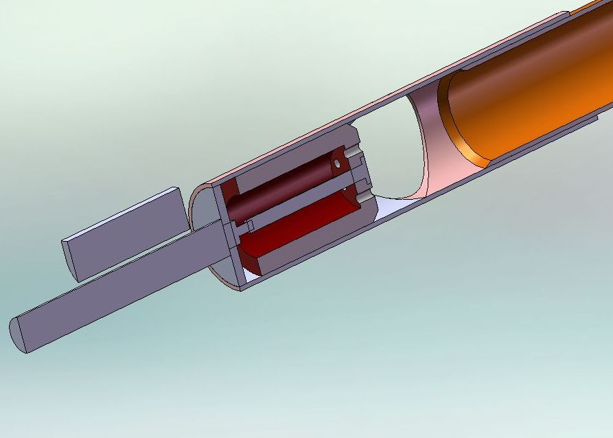
I’ve shot several potato guns. Some were the PVC / hairspray / BBQ lighter type. One was welded stainless steel, powered by compressed air with an solenoid valve for firing. I’ve wanted to build my own pnumatic cannon for years. Ammunition will be tennis balls rather than potatoes and the cannon will be breach rather than muzzle loaded. Electric solenoids will deliver the air to fire the ball as well as open and close the breach using an air cyclinder. With a big air tank and ball feed, the cannon will be capable of automatic firing.
For this project I considered using 555 timers to control the valve timing. Instead decided to use an Arduino which will initially be more complex, but will allow easier tuning of the valve timing and a variety of firing modes. I will go further into the electronics in a future post.
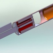
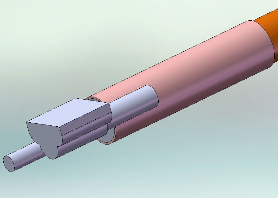
The image above is my drawing of the relay / transistor board that will allow the Arduino to control the solenoid valves. Below are some CAD models. The air cylinder that will close the breach is on the left with the valve that admits the firing air above it.
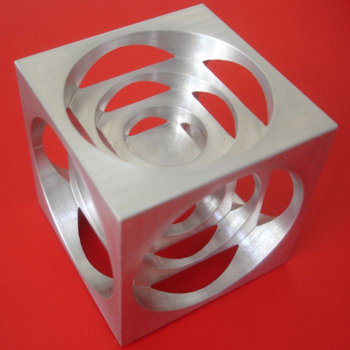
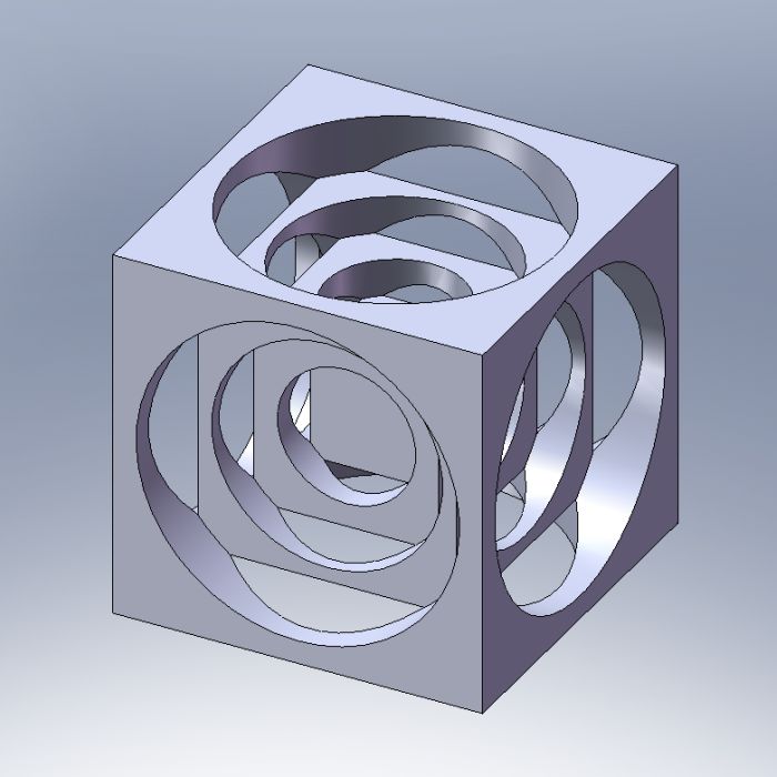
Turner’s cube

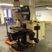
The turner’s cube is a traditional project for an apprentice or student learning lathe work who would be given one and told to reproduce it. I made this one on a CNC mill. Getting the diameters and depths correct for an aesthetically pleasing cube is more difficult than it would seem so I after an initial attempt doing it off the cuff on a 1″ cube I did some computer drawing before starting this 1-1/2″ cube.
Thanks to Bob Warfield for inspiration:
Excavator
I’ve had an idea for awhile to build a mini-excavator. (For a sense of scale the arms are 11″ long.) Nothing past the concept stage yet. This is designed to use steppers and timing belts to control the three joints. 3mm HTD timing belts, 72 and 15 tooth pulleys. 4.8:1, 23.04:1, and 110.592:1 gear ratios on wrist, elbow and shoulder respectively. (Double reduction on the elbow and triple reduction on the shoulder.) I thought about using linear actuators like a real excavator but screw type actuators have limited travel for their overall length and pneumatic or hydraulic cylinders would be more difficult to control electronically. I need some kind of positioning feedback (linear / rotary encoders or potentiometer) and pulse width modulated valves. Steppers (with the reduction) will have the torque I need and will be easy to control with no position feedback.
Johnny Van
A lazy afternoon in front of Alek’s shop.
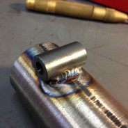
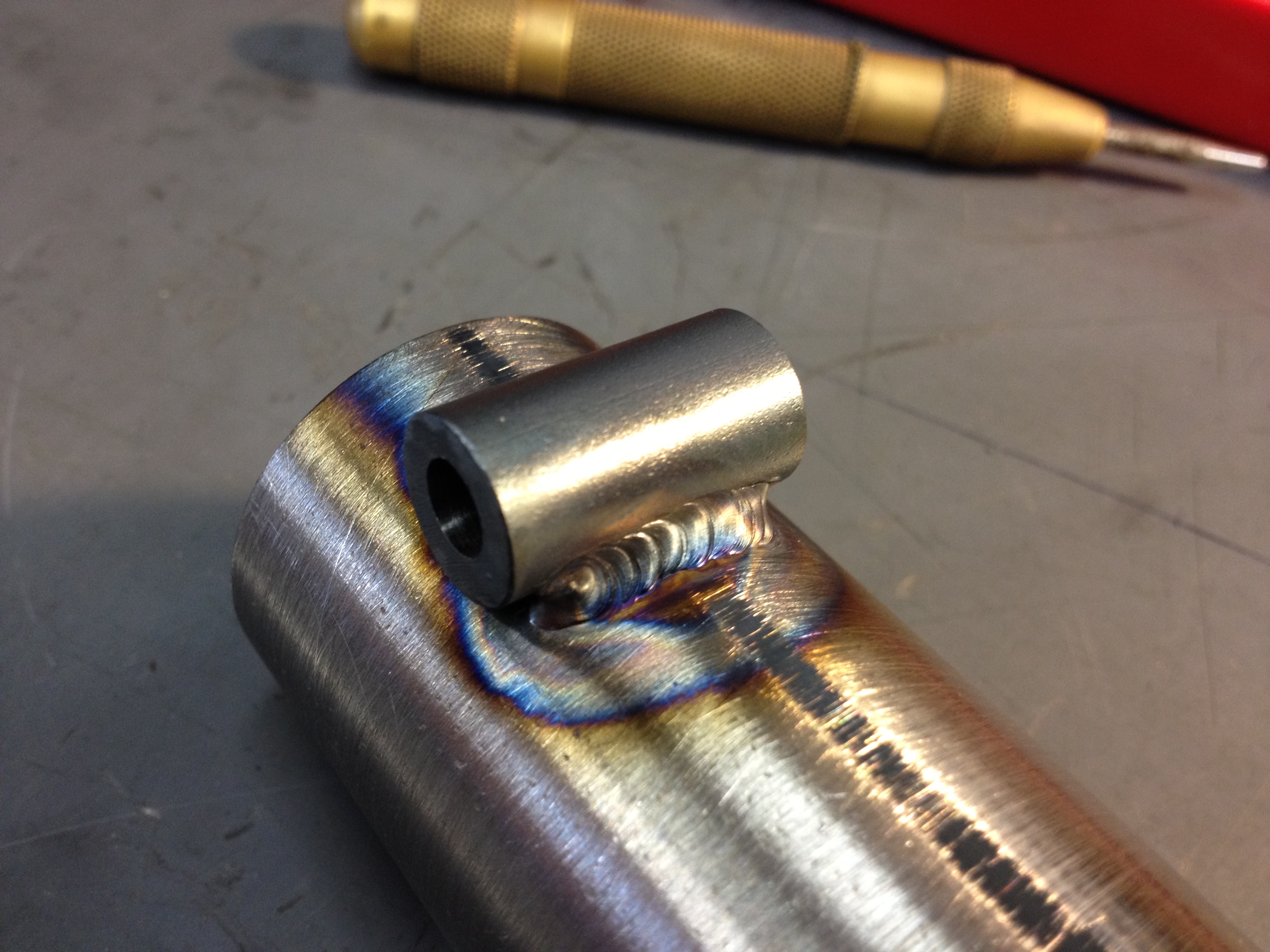
Timing Pulley
I had heard of DIY timing pulleys made by drilling a circle of holes in a piece of material and then turning down the piece to form the teeth. SDP/SI has some great info on pulleys including a chart of tooth profiles (http://www.sdp-si.com/D265/HTML/D265T015.html) and a center-to-center distance calculator (http://www.sdp-si.com/cd/default.htm). The HTD series of belts looks like it has the roundest teeth so it is most appropriate for this machining method. The calculator will tell you center-to-center distance for two timing pulleys but it also gives the pitch diameter.
This is a test part so I estimated the drill size from the drawing and drilled right on the pitch diameter. Instead of turning away the unwanted material on the lathe I used a milling machine to remove it away with an endmill. The pulley diameter is the same as the pitch diameter which seems to coincide with the info in the SPD/SI catalog. The drill size, hole circle diameter and pulley diameter can all be tweeked once I have the belts to compare with the pulley